Check out these two links great info on this:
http://www.wcb4x4.com/tech/diyrockcrawler.shtml
http://www.fordification.com/tech/power ... 00-4WD.htm
Before I jump into how I accomplished this I have to say at first I just wanted to mount the 79 Bronco box near the trac bar bracket just like it is on the 78 and 79 full size Bronco, but it was so close to my oil filter that it would not make it possible to change the filter! My truck has a 390 with the oil filter adapter putting it in the horizontal position. Other combinations may allow the box to mount in this position, but it would not work for me. If you could mount the box in that position you would not have to trade the worm gear/rack.
Now on to how I did it:
1. I followed the directions in the WCB link above on swapping the worm gear/rack. No need for me to show any pics or go on about it as they a superb job in their link.
2. I cut out some of the inner fender to jockey around the box and figure out the best placement/angle. Notice I cut out way too much because I tried to fit it further back the first go ‘round!
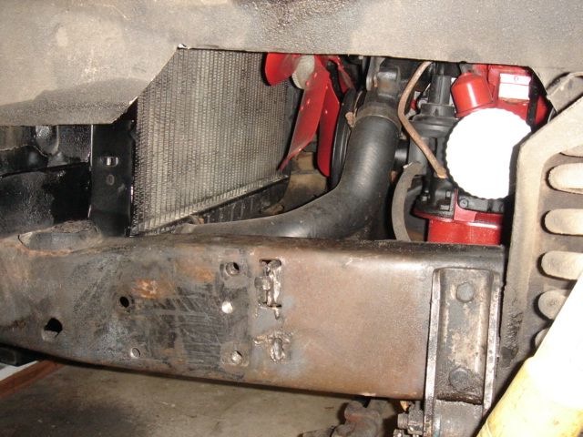
3. Next I placed the box in position using the existing rear most bottom bolt hole.
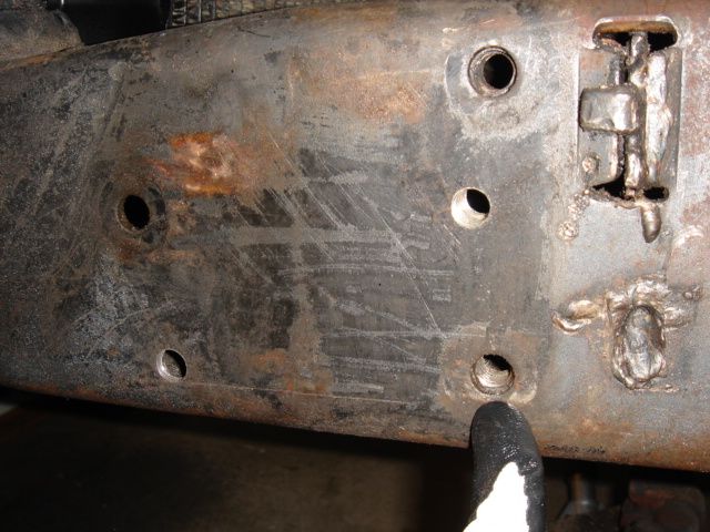
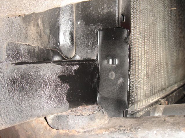
4. To get the box to lay down in the front I realized I needed to cut some of the radiator support out, knock the body mount forward some, re-weld the joint, and shoot some paint for protection.
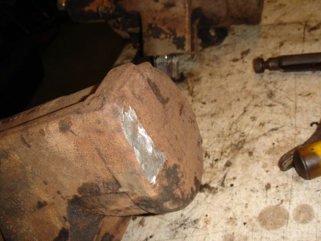
I also had to grind a bit of the front of the steering box.
5. Once I got the box at the angle I liked I used it as a template to drill a new forward most hole.
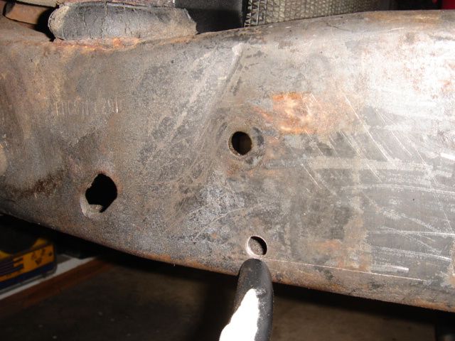
6. At this point you should have two bolts to hold the box in place. While in place for the third hole I drilled a 27/64” hole thru the box, frame, and thru the plate that is on the inside of the frame. Next remove the box and drill the hole to 9/16” and tap the hole in the frame to receive the original bolt (1/2” – 13). I did this rather than use the existing hole in the box so I could bolt it to the plate inside the frame like it was from the factory (just in a new place). In these pics you can see the new bolt placement compared to the existing and the new tapped hole.
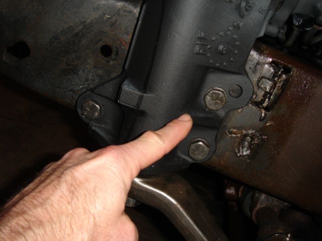
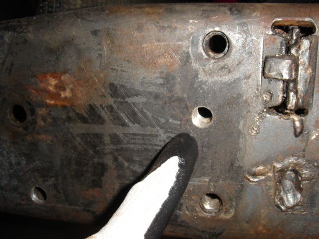
7. Once the box was in I used the original Pitman arm and draglink. Surprisingly I did not even have to adjust anything! Steering wheel ended up dead level just as before. I don’t know if everyone will be as lucky as me. In the past my truck had some kind of power ram assist that was cobbled together to the manual box. Did that make my life easier? I don’t know!
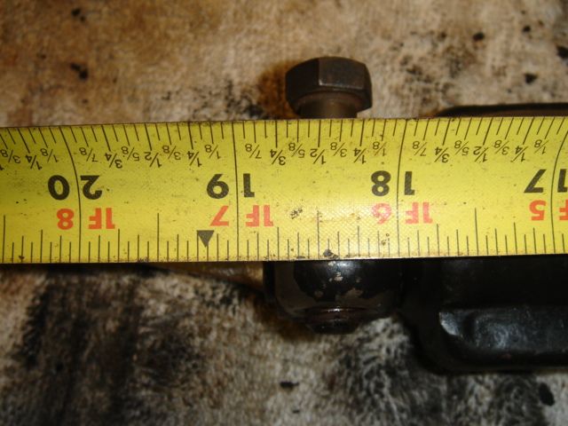
8. Now that that was out of the way all I had to do was fashion some kind of steering shaft. It went surprisingly easy also. I used a combination of the two wheel drive box shaft and my original shaft. Basically I cut the 2wd shaft just below the rag joint and my original shaft far enough below the u-joint to insert into the 2wd shaft 2-14”. I did all of this for a measurement of 18-3/8” from center line of bolt to the flat part of the u-joint cup as shown. That was with the tulip coupler collapsed and the double D slip portion extended. You should do your own measuring to verify shaft length required.
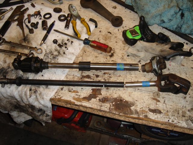
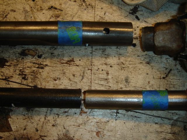
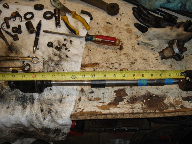
9. For some reason I had to use my original tulip joint to fit on the new steering box. To make it work on the new shaft I had to grin the pins down maybe a 1/16” each side.
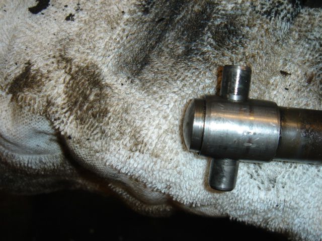
10. I welded all around where inserted and also did four 3/8” diameter rosette welds. Wallah…new shaft.
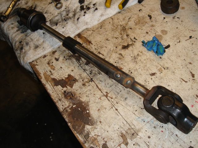
And ready for paint:
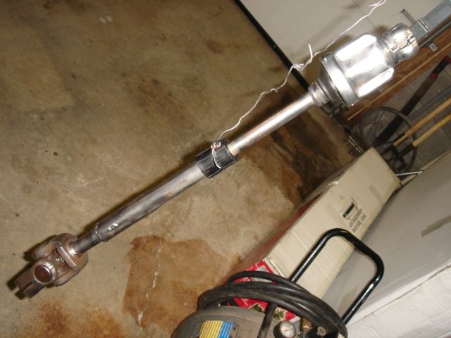
11. Connect hoses and bleed as described in the WCB link above.
I love my new power steering!!! It’s a joy to drive with 33’s!
Let me know if you have any questions,
Tyler

