|


|

|
|
|
How
to Shorten Your Manual-Steering Column |
|
 |
|
|
NOTE
1: This
tutorial is a companion to How to install power steering
in your 2WD '67-'72 Ford pickup.
NOTE
2:
PS = power steering; MS = manual steering
As
noted in the above-mentioned tutorial, Ford started putting the
Saginaw power steering box (which replaced the Bendix style box)
into their trucks starting in '68 and by '69 the Saginaw box was
used exclusively for all power steering applications. The Bendix
box was was prone to overheating and seal failure, issues
eliminated with the introduction of the Saginaw. However, while
the Bendix box was dimensionally identical to the manual
steering box, making it an easy upgrade, the Saginaw was 2
inches longer, which meant the steering column for PS-equipped
trucks needed to be 2 inches shorter to compensate. Just so that
you're up to speed, you simply have to remember that there are
three different steering column shaft lengths:
- Manual steering:
35-5/8" ('67-'70) or 36-1/8" ('71-'72)
- Bendix: 34-15/16"
- Saginaw: 32-7/8" ('67-'70) or 33-3/8 ('71-'72)
Since a good percentage of '67-'72 trucks have manual steering,
one of the first modifications new owners often make is to
convert their trucks to PS. Normally this is a simple swap, by
finding a PS-equipped truck and swapping in the shorter PS
column and the Saginaw box as a pair. However, it IS possible to
shorten your existing MS column if you're having problems
finding the right parts, and you're handy with a welder. This
article will show most of the details for what needs to be done
and begins after the steering column is removed and on the
workbench. For the purpose of this tutorial, I completely
disassembled a '67 MS/automatic column, a '71 PS/automatic
column, and a '68 MS/4-spd. column.
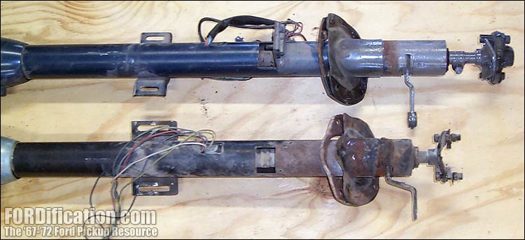
The
steering columns shown in Fig. 1 reveal the problem: the MS
column is obviously longer, to reach the shorter MS (or Bendix
PS) box. Let's fix that.
Steering Column Disassembly
1) Remove the steering wheel with a puller.
2) Remove the spring under the wheel and then pull the
main shaft out. When you do, the upper shaft bushing will be
slid off the shaft. Don't lose it if you're planning on reusing
it.
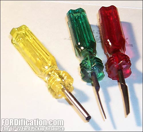
3) Remove the turn signal switch. In order to slide it
out of the column, you will have to first remove the harness
connector from the wiring at the base of the column. You'll need
a special tool to release the clips holding the pin connectors
in the switch's wiring harness, like the yellow-handled tool in
Fig. 3. This set of three cost me less than $7 at the local
parts store. Make a diagram showing the proper position for each
colored wire in the harness connector (so they can be
reinstalled correctly) and then use the tool to release each
wire from the connector.
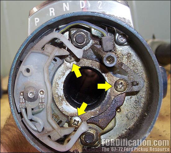
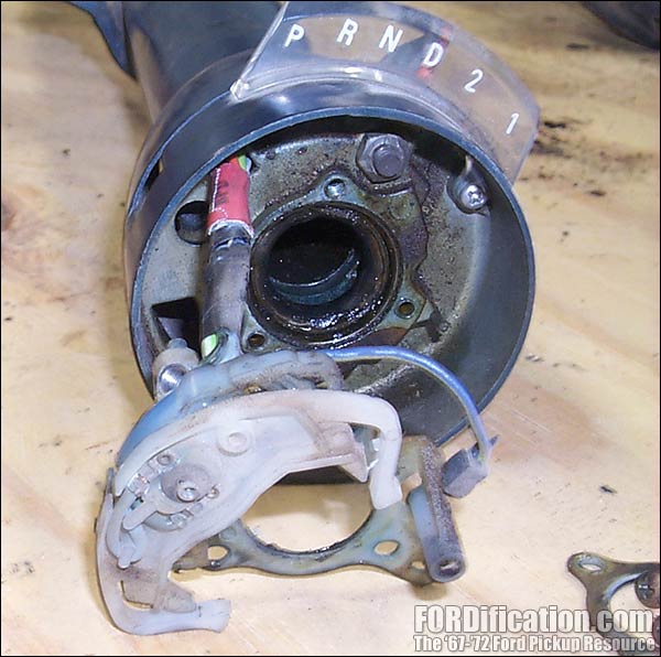
4) Remove the three Phillips-head screws holding the turn
signal switch retaining plate (Fig. 4), and then pull the turn
signal switch out of the column.
5) Remove the two 3/8" nuts holding the turn signal
switch housing and shift collar to the shift tube (these bolts
can be seen in the 12 o'clock and 6 o'clock positions in Fig.
4.) and then set the turn signal switch housing and shift collar
aside. (It is not necessary to remove the shift lever from the
collar.) When you remove these pieces, the two bolts will
probably drop out...be sure not to lose them. These are each
held in place in the shifter tube by a gob of thick grease for
installation (Fig. 5).
6) Slide the shift tube out of the column housing. When
it's removed, you'll be able to remove the shifter linkage lever
at the base of the column. Make a note of how it's oriented to
the column (see Fig. 11). Turn the housing upside down and dump
out the shift tube return spring.
7) Slide the firewall mounting plate and gasket off the
housing.
That's it! Your steering column is disassembled and ready for
modification. Let's take a few moments and compare the pieces
from a MS column and a PS column. |

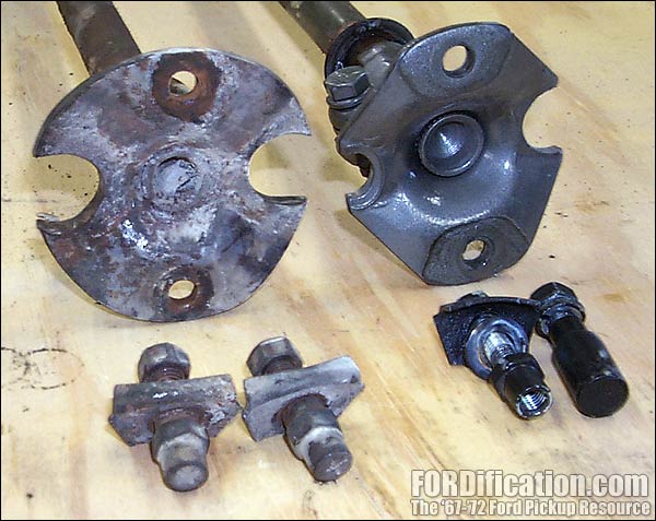
Fig. 1 - Top: MS column; Bottom: PS
column

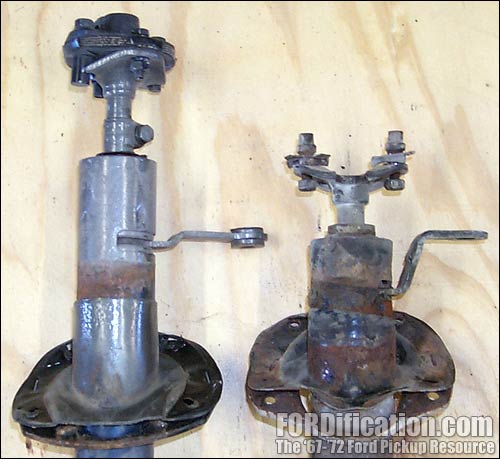
Fig. 2 - In this photo you can also see the
difference between the shifter arms. (Left: MS; Right: PS). The
steering wheel end of these columns are perfectly lined up with
each other for this shot.

Fig. 3 - This is a set of wire
terminal removal tools. The yellow-handled tool is needed to
release the pin connectors from the turn signal switch harness
connector.

Fig. 4 - Removing the turn signal switch retaining
plate screws.

Fig. 5 - This shot shows one of the two bolts
which hook onto the shifter tube and are held on with thick
grease, to hold them in place during installation.

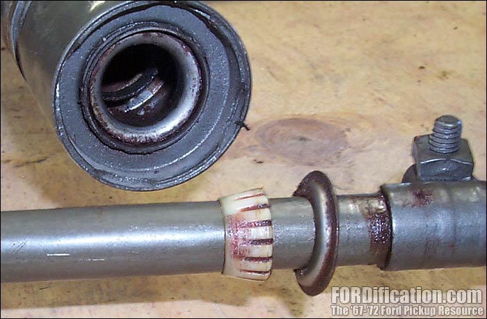
Fig. 7 - Here's a shot of the plastic bushing on the
flange-end of the steering shaft, and the steel race it rides
on, in the end of the column. |
|

Fig. 8 - Just another FYI reminder, repeated from the PS
tutorial: '71-'72 column shafts have some extra material on the end
of the shaft that will need to be removed if using a '67-'70 3-spoke
steering wheel. |

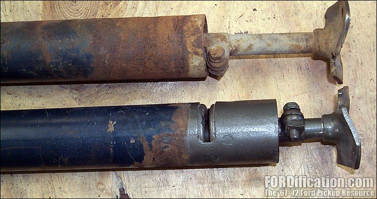
Fig. 9 - Here's a comparison of the shift linkage levers at
the base of the columns. Since the PS column is shorter, it's lever
(top) has to have a more-radical bend to reach the shifter linkage
than the MS linkage (bottom). The MS lever can be bent to match the
PS lever, if an appropriate PS lever is unavailable. |

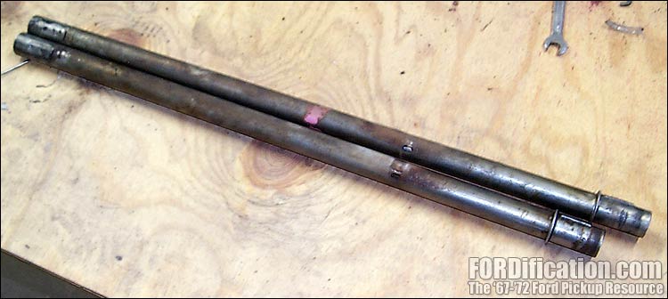
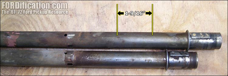
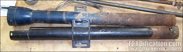
Fig. 10 - Here's a comparison of the two shifter tubes. The
main steel steering shaft runs down through these. The MS shifter
tube is on top, the PS shifter tube is on bottom. The PS tube is
exactly 1-9/16" shorter than the MS piece. (See table of
measurements below.) |
|

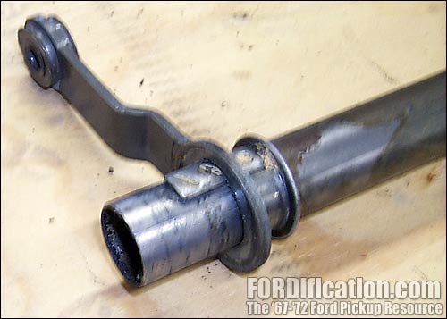
Fig. 11 - The shifter linkage lever slides onto the end of the shifter
tube. A large spring at the bottom of the column housing slides over
the end of the shifter tube and pushes against this lever. There is
a similar locating tab on the other end of the shift tube, to
properly locate the shift collar. |

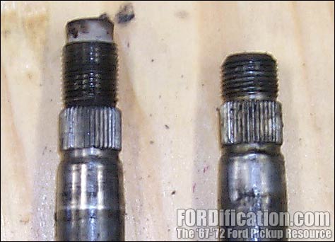
Fig. 12 - The flanges on the end of the column shafts are
slightly different between early and late columns. The early shafts
(right) use one large and one small locator pin, whereas the later
shafts (left) use two large pins. Make sure you use the pin setup
which matches whichever shaft you decide to use, or modify the
flange with a die-grinder as needed. |

Fig. 13 - Shown here are the two slightly-different styles
of inner firewall retaining plates. The plate and gasket for a MS
setup is on the left, the PS pieces are on the right. Because of the
different angle of the PS steering column where it comes through the
firewall, the PS plate had to be heightened a bit. If you're handy,
you can either modify your existing MS piece or just cut a new one
from flat sheetmetal and reuse your existing gasket. |
|

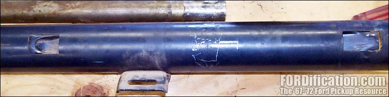
Fig. 14 - This picture shows the amount the longer
shifter tube will have to be sectioned and the best location for
the cut. Using a chop saw will make this cut quickly and very
square with the tube.

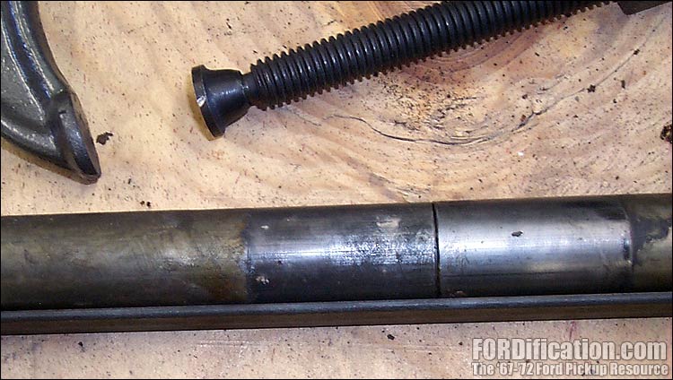
Fig. 15 - Once you section out the necessary amount from
the shifter tube, clamp them together onto a piece of angle
iron, to hold them square to each other when welding them back
together.

Fig. 16 - Shown here are the Late style of lower bushing
retainer (top) and the Early style (bottom).

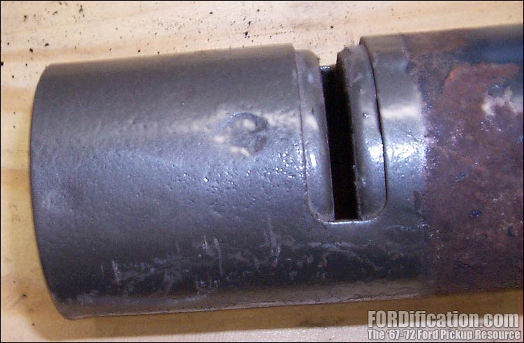
Fig. 17 - Here's a view of the slot for the
shifter linkage lever. You can see the spot welds holding the
insert in the end of the main housing tube.

Fig. 18 - Reinstalling the turn signal switch.

Fig. 19 - Here's a view of the channel that the turn
signal wiring harness is fed through, along the bottom of the
main column housing. |
Sectioning the Shifter Tube, Main Shaft
and Main Housing
What
we're looking to do now is section the three pieces that are too
long: the column housing, the shift tube and the shaft itself.
Don't worry, it's not as complicated as it sounds. Sectioning
simply involves cutting a chunk out of the middle, discarding
it, and welding the two halves back together. If you've got a
welder and know how to use it, you can easily accomplish this in
an afternoon. Here's a chart that shows the
factory dimensions of the various column pieces:
| |
Power Steering Column |
Manual Steering Column |
|
Shift Tube |
26-11/16" |
28-1/4" |
|
Shaft
(1) |
31-1/4" |
34" |
|
Column Housing |
28-1/16" |
30-7/16" |
|
(1)
- Measured from top of splines to top of flange lip |
The
shaft and the hollow column housing and shift tube each need two
things done to it: the appropriate amount of material sectioned
from the middle, and to be welded back together.
In
Fig. 14 I've laid both MS and PS shifter tubes next to each
other, and you can see the amount of sectioning needed and the
best location for it. The holes in each each tube just at the
left side of the picture are for the neutral safety switch
actuator, so your cut will have to be between those holes and
the rib which holds the shifting linkage arm.
For
cutting each piece, keeping the cut perfectly square is very
important...therefore you should use something like a chop saw
or band saw (if the band saw has guides which hold the piece
perpendicular to the blade). After making the two cuts, clamp
the two pieces together onto a length of angle iron (as shown
for the shifter tube in Fig. 15), which will not only hold them
steady for you for welding, but will ensure that the two pieces
are square to each other, and will prevent them from warping
while you're welding. However, it's probably best to put at
least three quick spot welds around the circumference of each
piece before completing the weld.
Repeat this process for the main steel shaft. With the shaft,
your section can be cut out pretty much anywhere along it's
length. After you make the cut, bevel the two ends a little
which will be welded together, for best weld penetration. After
the weld is made and cools off, you'll need to grind it down
smooth, since the bottom shaft bushing and bushing retainer will
need to be slid all the way down from the top. The plastic
bushings are slit, so they can give a little in case the
weld isn't ground down perfectly smooth. However, there is either a
clamp or a collar at the end of the shaft which holds the
plastic bushing, depending on if you're using an early or late
main shaft (Fig. 16), and the weld must be smooth to allow the
collar (on the Late style) or the bushing base (Early style, see
Fig. 7) to slide on.
And
finally, on to the main housing. There are two ways to do this.
The easiest way is simply to section out 2-3/8" of the tube,
between the shifter linkage lever's slot and the dash bracket,
and then weld the two halves back together.
As
seen in Fig. 17, the end of the main housing has an insert,
which is spot-welded into the end of the housing, in 8-10
different spots. (You can see these spot welds in Fig. 17.) The
insert holds the lower bushing race and also serves to hold the
shifter tube spring. If you wanted, you could simply cut off the
last 2-3/8" of the housing's tube and then use a spot-weld drill
bit to drill through the welds in the outer tube but not going
through into the insert. Then you can slide the insert out,
drill a few new holes in the new end of the housing, slide the
insert in the end of the main housing, and re-weld it using the
holes you just drilled. You'll also have to cut the 5/8"-wide
slot for the shifter linkage lever. This second method does
require more work, but less welding. However, I'd suggest simply
sectioning it like you did with the main shaft and the shift
tube....and be done with it. |
|
Steering Column Reassembly
Once
the main housing is welded back together, cleaned up and the
main housing painted (if applicable), you're ready to
reassemble...which is basically a reverse order of disassembly:
1) Install the firewall retainer plate and gasket onto the
main housing.
2) Drop the large return spring down into the bottom of
the main housing.
3) Slide the shifter tube down from the top to the point
where you can see the end of it through the shifter linkage
lever slot. Insert the lever into the slot and rotate the
shifter tube to align the tab on the tube with the notch in the
lever (see Fig. 11), and then continue sliding the shifter tube
down against the spring. (You do have it oriented correctly,
don't you?)
4) Using some very thick grease (or similar substance),
hook the two bolts (which will hold the turn signal switch
housing and the shift collar) onto the holes in the shift tube
(see Fig. 5). You could also use something like masking tape to
hold the two bolts in place. Then install the turn signal
switch housing and the shift collar. The end of the shifter tube
has a locating tab that slides into a groove in the shift
collar.
5) Slide the turn signal switch wiring down through the
appropriate hole in the housing and shift collar. Continue
working it through the channel along the bottom of the main
housing (Fig. 19) and out the end of the channel. Reinsert the
wires into their respective place in the harness connector.
6) Install the lower clamp/collar and plastic bushing (if
removed) onto the main shaft. Slide the shaft into the main
housing from the bottom.
7) Slide the upper bushing down onto the main shaft,
against the race in the turn signal switch housing.
8) Re-install the steering wheel.
9) Loosely re-install the entire column into the truck.
Once you have the column connected at the rag joint and the
bottom of the dash, slide the main housing as far into the cab
as possible to seat the upper bushing, then slide the lock
collar/clamp at the flange end of the column up as far as it
will go, and tighten.
10) Tighten down all bolts, reconnect the turn signal switch
wiring into the main harness....and you're done!
I
didn't go into EXTREME detail here, but I figure that if you're
at all mechanically-inclined, you should be able to figure out
the smaller details as you go. It's actually very basic, and as
long as you pay close attention to how things come apart,
they'll go back together just as easily. |
|
Another option...using a 4-spd. column
Here's another idea that might be just the ticket for your
truck. I also disassembled and measured a floor-shift 4-spd
manual steering column and found something very cool...the
column is already shortened to the length you need it! If
your truck is already equipped with a 4-speed, it's very
possible that you've also got the correct column, and all you
have to do is section your existing shaft or swap in the main
steel shaft from a PS column. If your truck is an automatic and
you want to install a floor-shifter, this could very well save
you a lot of time as well, since, once again, all it requires is
swapping in a PS main steel shaft (or sectioning the existing MS
shaft), since there's no shift tube, and no sectioning is needed
for the main housing.
|
NOTE: Be sure to check out 'The Manual
3-spd Steering Column Explored' page,
which is a similar photo collection of the teardown
of several '3-on-the-tree' steering columns.
If you have any additional information that you feel
could be added to this page to help out fellow Ford
truck owners, please feel free to
e-mail me. |
|

Fig. 20 - Here's a comparison photo of a 4-speed MS
column (top) and a MS/automatic column. You can see that the
4-speed's column housing is already short enough to use the
shorter PS shaft.

Fig. 20 - Here's a comparison photo of the 4-spd MS main
housing (top) and the PS automatic column (bottom). As you can
see, the 4-spd column housing is already at the desired length
to install the shorter PS shaft. |
|
 |

Want to link to
this site? Please save this banner to your hard drive to place on your
webpage.
The correct link to use is
http://www.fordification.com
|