|
On January 2004, I purchased a 1967 Ford F100 SWB Ranger truck.
It has a 352 FE with a MX transmission behind. At the moment the
truck is undergoing a frame off restoration. One point of this
restoration is the change from the present front drum brakes to
disc brakes. For this I bought a complete disc brake conversion
kit from Master Power Brakes.
|

Fig. 01 |
The included spindles were 1975-79 types. I thought that for
$1045.00 everything should be complete and in best quality. Far
from it! There were no dust shields as pictured in their
catalog. The second and even worse fault was the condition of
the LH spindle. The lower bore for the king pin bushing was
extremely corroded. Because of this corrosion the diameter was
increased by about 1mm (0.04"). Moreover the thrust face for the
bearing was also worn out 1mm deep. Due to this situation, a
standard rebuilding with the replacement of the king pin
bushings would’ve been impossible.
Of course I made a complaint to MP Brakes regarding this
problem. After many emails with a lot of explanation and
pictures, they agreed to send another LH spindle for free, but I
had to pay the shipping costs. The new LH-spindle had an
accurate bore but it was a 1973-74 type instead of a 1975-79
type. Now I had a good 1973-74 LH-spindle and a good 1975-79 RH
spindle. I got mad!! 1973-74 spindles have other king pin
dimensions as well as other bump stop features than the 1975-79
spindles. I don’t think it’s a good idea to use two different
spindle types for one truck.
After a lot of study, I decided to turn new bigger bores into
the spindles on my lathe and to fabricate new bronze bushings
for the kingpins to match. Now it's time for some pictures:
|
|
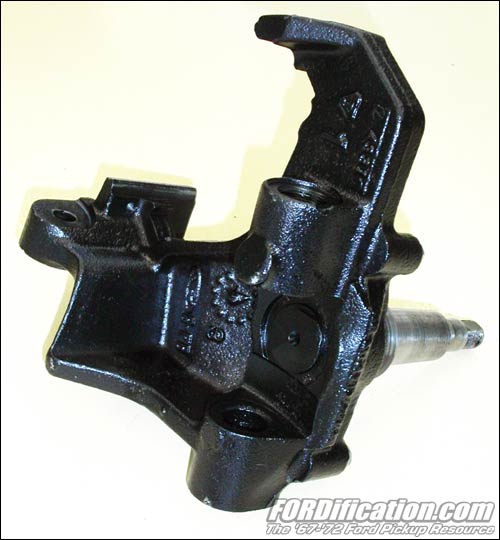
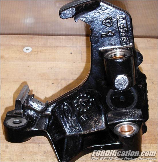
Figs. 1 and 2 show the defective LH spindle. On the first view
it looks very clean..... but it isn't. The lower bushing bore as
well as the face for the thrust bearing are corroded and worn
out very badly. |

Fig.
02 |
|
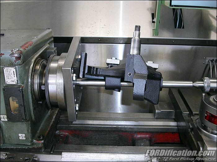
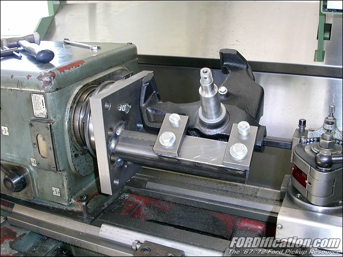
Figs. 3 and 4 show the device which I had to fabricate to clamp
the spindle on the lathe. To find the correct center, I used a
rod thru the existing bores. After this I welded a strong
support with two ears on a thick steel plate. The steel plate
was fastened with four screws on the lathe chuck. The spindle
was fastened to the support ears with two screws. I used the
threads for the dust shields. |

Fig.
03 |
|

Fig. 04 |
|
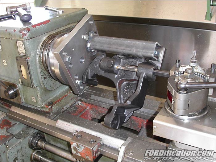
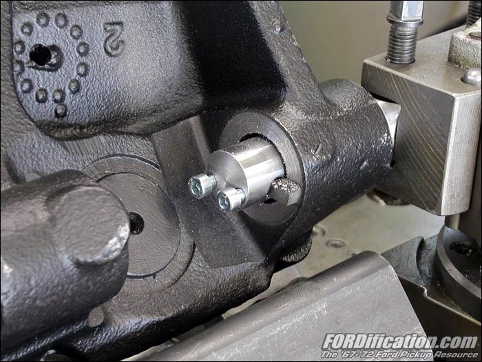
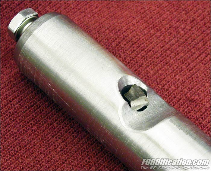
Fig.
5 shows how the cutting tool goes into the upper bushing bore.
It was very important to do the upper as well the lower bore in
one chucking because of a perfect lining of the center axis. It
was also important to cut from the middle part to the outside in
a manner that the threaded ends of the bores were left
untouched. These threads will be used for the standard threaded
end caps with grease nipples. The diameter of the bores are
approximately 27.5mm (1.083"). |

Fig. 05 |
|
Fig.
6 shows the cutting of the face for the thrust bearing. The
removed material will be replaced with a made-to-measure washer
of about 1.7mm (0.07") thickness. I needed to fabricate the
pictured cutting tool by myself. The blade of this tool has to
be inserted after the rod is already pushed thru the bore. |

Fig. 06 |
|
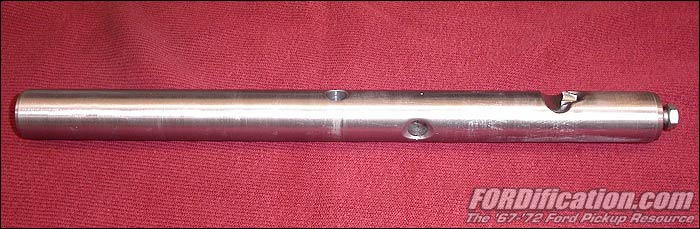
Figs. 7 and 8 show the remanufactured spindles. After the LH
spindle was completed successfully I decided to do the RH
spindle in the same way. Both spindles are now ready to receive
new custom-made bushings. |
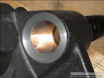
Fig. 07 |

Fig. 08 |
|
The next step will be to obtain a suitable piece of bronze and
to fabricate the bushings as well as a device to line them up in
the spindles. |
|
Shown here is an almost-finished upper bushing just before
cutting. I found a supplier for non-ferrous metal who had a
suitable high-performance bronze tube in stock. I only needed to
cut a small amount at the inner as well as at the outer
diameter. I turned the inner diameter about 0.025mm (0.001 inch)
bigger than the king pin diameter. The goal was that no
additional reaming will be necessary after pressing in. For a
light press fit I chose the bushings outer diameters about
0.015mm (0.0006 inch) bigger than the bores in the spindles. |
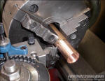
Fig. 09 |
|
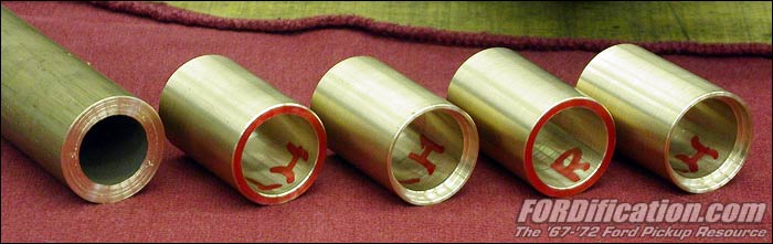
Here
are the finished custom-made bushings. The upper bushings have a
stepped face to hold the king pin seal. At left is the rest of
the raw material tube. |

Fig. 10 |
|
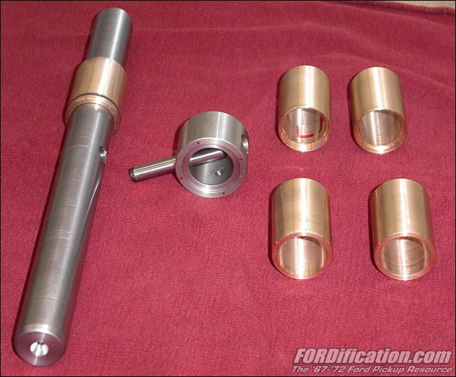
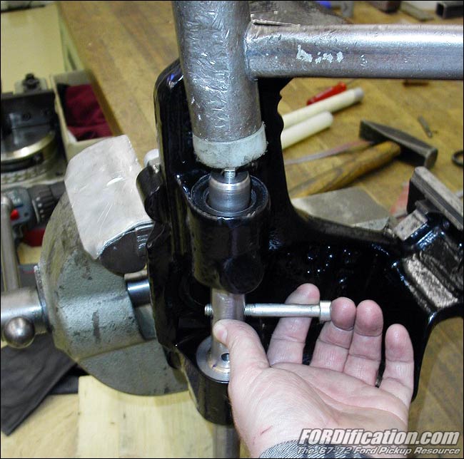
Figs. 11 and 12 again show the bushings as well as the device to
press in the bushings in the spindles. The device should
guarantee that the bushings are absolutely lined up after
pressing in. For this I fabricated a guiding sleeve with an
o-ring. The sleeve is only needed for a guided installation of
the first bushing. The outer diameter of the guiding sleeve is a
little smaller than the bushings. It can be installed by hand
and is held in the bore by the o-ring. After the installation of
the first bushing, the sleeve can be removed. The
already-mounted first bushing guides the press rod for the
installation of the second bushing. |

Fig. 11 |

Fig. 12 |
|
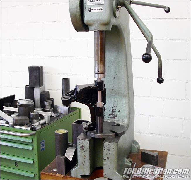
This
is the ram press which was used for the installation of the
bushings. This equipment is located at the company where I work.
This is the only picture because I needed both hands for
operating the press as well as holding the spindle at the same
time. For additional safety I brushed the bushings with
LOCTITE_641 adhesive before pressing in. |

Fig. 13 |
|
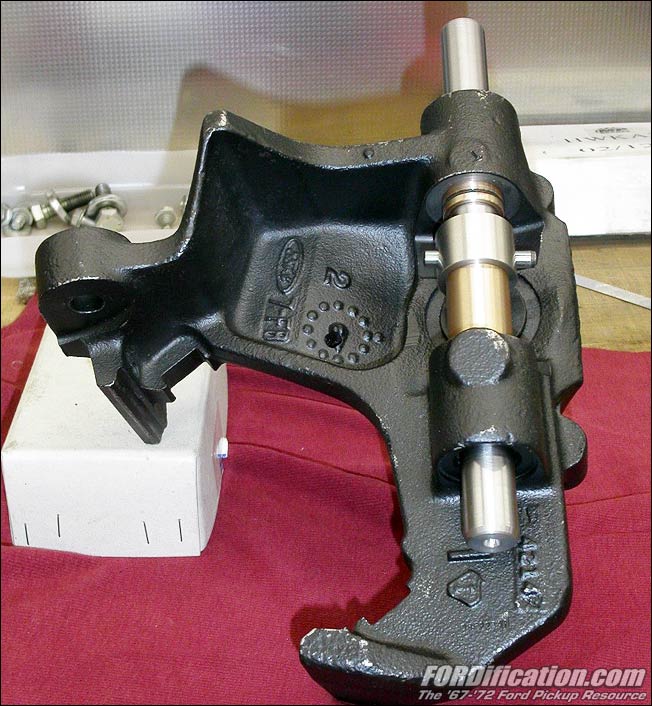
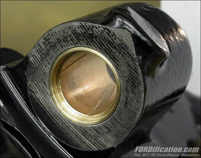
Here
is the LH spindle with pressed in upper and lower bushings. The
RH spindle was made in the same way. |

Fig. 14 |
|
Reaming the grease grooves as well as adding the washers for the
thrust bearing will be the last part of this story. |
|
Figs. 15 and 16 show the self-made tool to ream the grease
grooves. I thought a lot about how to get these grooves in the
bushings. According the original bushings, the grooves should
have a helical path along the inner shell of the bushing. I
guess that the helical path of the groove results a better
distribution of the kingpin's pressure force. I found that the
following method gave really nice results. I took the shaft from
the pressing device (see Fig. 11) and had it modified so that I
was able to insert a tiny cutting edge. It was a hard job to
grind this little thing by hand. The square-profile of the blade
measures 6x6mm (1/4"x1/4"), the length about 20mm (3/4"). As
many other guys in the later forties, I found out that the
glasses should be changed to better ones. The blade is mounted
so that its' cutting edge is 0.3mm (0.012 inch) above the
circumference of the shaft. This measurement will give the depth
of the grease groove in the bushing. |

Fig. 15 |

Fig. 16 |
|
Fig.
17 shows the tool in action. I used the nylon hammer with light
strikes on the upper end of the shaft. Due to the inclined
fixation of the blade as well as light turning moment by hand at
the shaft, the grease groove gets its helical shape in the
bushing. Each bushing receives three grooves evenly spaced.
|

Fig. 17 |
|
Here's the finished upper bushing. The picture also shows the
stepped diameter for the retaining of the king pin seal. |

Fig. 18 |
|
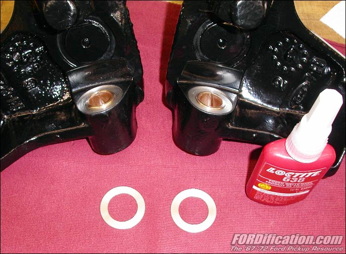
Picture #19, #20 show the addition of the made to measure thrust
washers. As described earlier, I had to rework the spindle faces
for the thrust bearing. The removed material needs to be
replaced in such a way that the distance between the bushing
lugs is correct again. I fabricated two washers with a thickness
of 1.7mm (0.07 inch) and pasted them with LOCTITE 638 to the
machined thrust face of the bushing lug. |

Fig. 19 |

Fig. 20 |
|
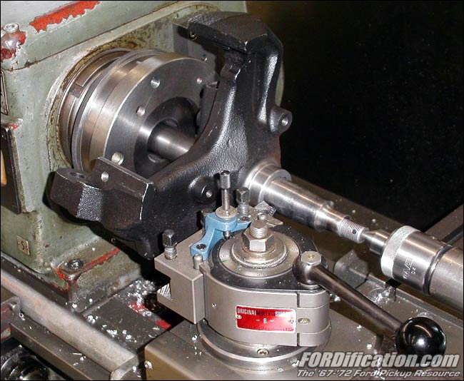
Picture #21 shows the spindle in the lathe again. As a final
work I reconditioned the thrust face for the inner rotor bearing
as well as the surface for the rotor seal. |

Fig. 21 |
|
That's it! The spindles are now ready to use and should be
within the original specifications.
Special thanks to forum member ‘jor’, who has helped to make
this text readable. |