FORDification.com
   (powered by Google)


  HOME

  Technical Articles

  Factory Literature

  Discussion Forums

  Photo Galleries


  Service Bulletins (TSBs)

  Decoding Your VIN

  Diagrams & Schematics

  Links & Resources

  In the Movies

  Downloads
  Member Meet & Greets

  In the Media

  Site Index

 MISC / PERSONAL

  My Truck Projects

  My Heinz 57 '67

  I've Been Censored!

  Contact


You are here: Home Tech Articles & Tutorials Steering / Suspension / Brakes Installing Disc Brakes on Your 2WD Pickup (Pt.2)
Back to Technical Index

Installing Disc Brakes on Your 2WD Pickup

PAGE  [ 1 ]  -  [ 2 ]

KINGPIN REMOVAL

     If you're planning on dropping off the axles, kingpins and spindles off at the machine shop (the recommended route), you can skip ahead to the Reassembly & Reinstallation section right now. However, if you're a masochist and want to save the money and do this all yourself, keep reading on....

     So...you're going to tackle the job of kingpin removal and replacement on your own. Well, be prepared to use a BIG hammer (aka BFH) and lots of heat (and more than a few loud four-letter words!) if you (or the previous owner) neglected to keep his front end properly lubed.


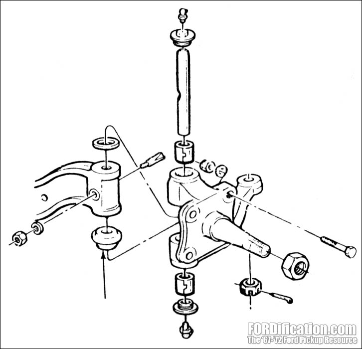
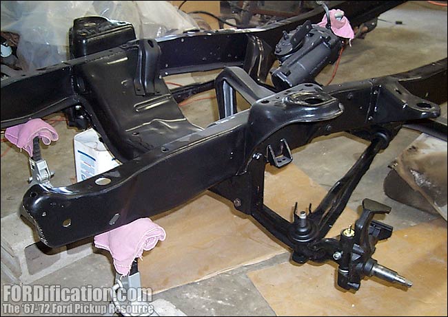
Fig. 1 - The kingpin bushings are located in the spindle only.


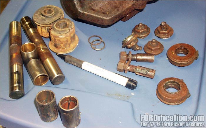
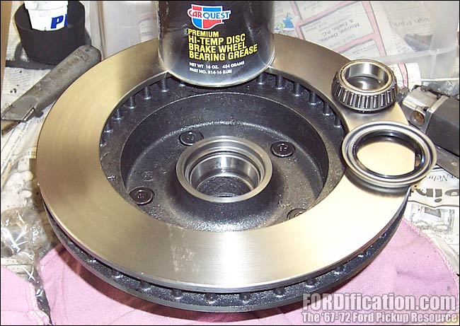
Fig. 2 - Here are all the old front-end parts: kingpins and retaining pins and bushings, axle pivot bushings, grease caps and shims.


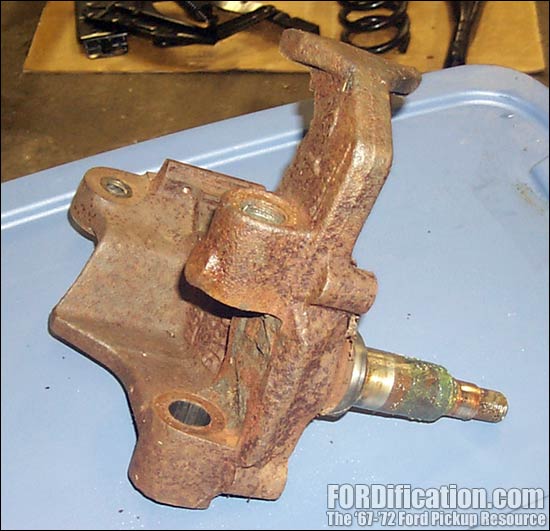
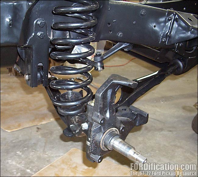
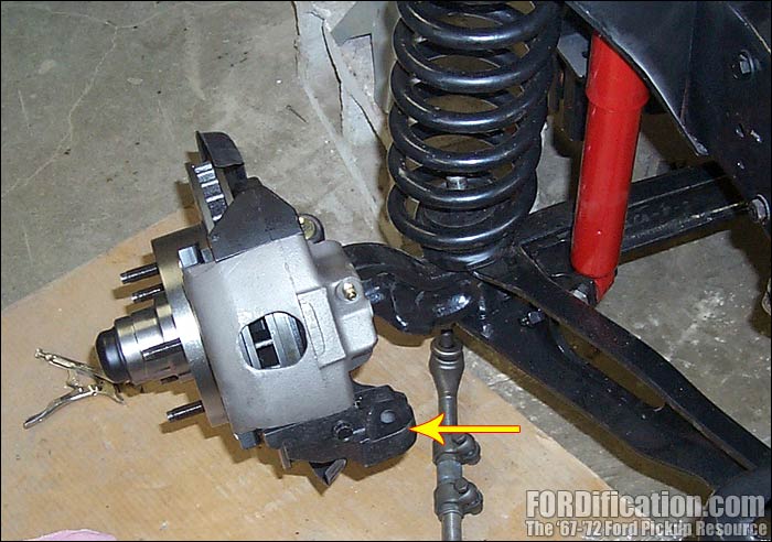
Fig. 3 - Here's the freshly removed spindle.


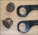
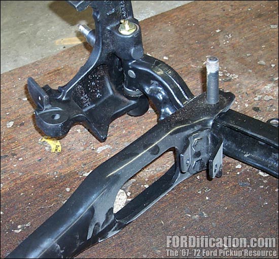
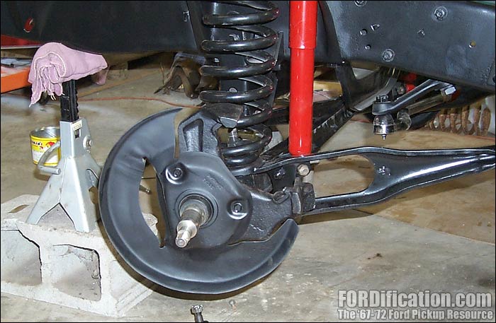
Fig. 4 - Be sure to replace the axle pivot bushings while everything's easily accessible.

     Start off by cleaning the whole kingpin region as much as possible, and then start by removing the kingpin's tapered locking pin. You'll remove a nut and then drive the pin out of the I-beam. Then remove the top and bottom grease caps to expose the ends of the kingpin. Wipe as much of the old grease out as possible. Since the kingpin is just a straight pin, it can either be driven out the top or the bottom. Be sure to wear safety glasses, as the kingpin is a hardened steel shaft and therefore brittle, and it's always possible for a misaligned hit to cause a chip to go flying.

     If the front end was properly lubricated during it's life,  the kingpin should come out fairly easily after the first couple of good hard whacks, but most people say that it takes a lot of pounding to get them moving. Once they do start moving it usually gets a little easier. The use of a brass drift with a slightly smaller outside diameter than the kingpin is highly recommended. Using a steel drift can also booger up the threads in the spindle necessary for securing the end caps. Just be careful to not mushroom the end of the kingpin, as further removal will be next to impossible! One nifty trick is to remove the upper grease cap and drill a 1/2" hole in the center of it, and then reinstall. You can then use a 1/2" drift to drive out the kingpin, with the grease cap acting as a guide to keep things centered and to protect the grease cap's threads in the spindle. And don't worry...your kingpin set comes with new grease caps.

     If your kingpins don't budge at first, you can start applying heat to the axle (not the spindle), being careful not to get it cherry-hot which could affect the temper of the steel, and attempt to drive the kingpin out using your BFH. You might find you'll have to break out the Liquid Wrench or PB Blaster and soak the heck out of everything and just let it set for a day or so before trying it again.

     Once the kingpins are out, start by cleaning up the kingpin bore in the axle using some emery cloth. (Do NOT use a brake hone!) Don't get carried away here...you just want to clean it up. Once you can lightly tap the kingpin into this hole with just a little resistance, stop! Repeat this process with the spindles' kingpin bores.

     Now you're ready to install the kingpin bushings. If you're using the plastic bushings, you should be able to tap them into the spindle using a block of wood. The bronze bushings will need to be pressed in and reamed to fit the kingpin and is a job best left for the machine shop. A brake hone will not get the job done, as the upper and lower bushings need to be done together at the same time. This is a fast and cheap job that you shouldn't attempt yourself without the proper equipment.

     Next, you need to replace the axle pivot bushings. These are pressed into the axle but can be done at home if you have access to a hydraulic press. Considering how very cheap the bushings are, replacing them should be done regardless of the old bushing's condition. Might as well do it now while it's easy access, right? I replaced my stock rubber bushings with PST's polygraphite bushings which required the use of the original outer shells. Since the machine shop messed up the shells of the original bushings when they were being removed, and considering new bushings were extremely inexpensive, I opted for buying a new set and drilling out the rubber portion and then just pressed the new shells back into the I-beam.

     Once the kingpin bushings are pressed in and reamed and the axle pivot bushings are installed, you can begin the actual reassembly...


REASSEMBLY & INSTALLATION

     Begin by installing the new kingpin, bearing, seals and shims. The bearing should be marked for proper orientation. Be sure to line up the notch in the kingpin with hole in the axle end for the tapered securing pin...(Incidentally, the bearing goes under the axle, and the shims, if needed, go on top of it) and then install the securing pin. Install the grease caps and lube the assembly. You're now ready to install the I-beam assemblies back onto the truck.

     Incidentally, this is a great time to install new radius arm bushings...considering how cheap they are, it would be senseless to reuse your old ones. Slide the radius arms onto the I-beams and insert the coil spring bolt (Fig. 5). Slide one of the radius arm bushings and washers on each arm and then lift each assembly back up into place with a hydraulic jack and insert the radius arm into it's bracket. Install the other radius arm bushing and washer and get the nut started. (Don't worry about tightening it down quite yet.) Insert the pivot end of the I-beam into it's frame bracket and install the bolt/nut. Insert the coil spring pads and coil springs, then gently lift the assembly with the jack until the spring's pigtail is resting in the spring tower's groove, and install the spring retaining strap. Now go ahead and tighten each radius arm's nut and remove the jack.

     From here on out it's pretty much a no-brainer. Simply install the disc brake dust shields on the spindles, then the rotors on the spindles. (You ARE using new bearings and seals in the rotors, right?) Secure the rotors and install the dust caps.

     Now we're ready for the installation of the steering linkage. Remember I told you back on Page 1 that you'd need to get the steering components from your donor truck? Well, here's why: the disc brake spindles' steering arm is thicker than the drum brake's, so the tie rod end's taper is going to be too short (Fig. 12). So you're either going to have to use all the steering pieces from your donor truck or do some grinding on the spindle's steering arm to remove about 1/4" of it's thickness (Fig. 13). I opted for  replacing all the steering components with new pieces, simply ordering pieces for a '79 F-150 and they installed without a hitch.

Don't forget to get your alignment checked before hitting the streets!


Fig. 5 - Install the radius arm onto the I-beam & spindle assembly and insert the coil spring bolt...


Fig. 6 - ...and then install the whole assembly onto the frame.


Fig. 7 - Next install the coil springs, cups and retaining straps. You can see the holes in the frame just to the right of the coil where the line brackets will be installed, but using newly drilled holes for the new brackets.


Fig. 8
- Here's a shot of the bare spindle with the disc brake dust shield installed.


Fig. 9  -  Here is one of the new rotors ready for a new inner bearing and seal...

Fig. 10
- ...and here's the new rotor and caliper installed. Looks good!

Fig. 11
- A shot of the installed front brake units. Be sure to check for proper wheel clearance!

Fig. 12
- Here's a view of the differences of the stock '67-'72 tie rod ends vs. '73-'79 pieces, where they connect to the spindle.

Fig. 13 - The '73-up spindle's steering arm is thicker than the '67-'72 versions.


     Congratulations! You now have most of the main hardware installed for your disc brake conversion. All that remains is to install the brake lines and associated hardware, like the proportioning valve. You'll have to drill holes in the frame to install the disc brake line brackets, and then to install the flexible lines to the calipers. These flexible lines should always be replaced. While they might look good on the outside, it's very possible that time hasn't been nice to them on the inside, and you'd never know it. Don't get cheap here...replace the lines!

Page 3 will consist of the necessary brake line bending and installation. While pre-bent brake lines are available from aftermarket sources like Inline Tube in both steel and stainless steel which includes all the proper fittings and armor around the tight bends, I've decided that for my project I wanted to bend my own. The last time I checked, Inline's price for standard steel lines for a truck was about $155, but the straight lengths of line and the necessary fittings at my local auto parts store, enough to do all the hard lines on my pickup front-to-back, came to less than $25. I'll probably have to go back to pick up some more lines after I get started learning how to bend and double-flare the lines, but I can easily handle that cost. For example, a 60" length of standard 3/16" steel brake line, already double-flared on each and with fittings, was about $6 at my local store. At the price, the education will be fairly cheap.

This will be the next phase of this project that I will be getting started on very shortly. Please be sure to check back to see the updates. Stay tuned!

PAGE  [ 1 ]  -  [ 2 ]


You are here: Home Tech Articles & Tutorials Steering / Suspension / Brakes Installing Disc Brakes on Your 2WD Pickup (Pt.2)


Want to link to this site? Please save this banner to your hard drive to place on your webpage.
The correct link to use is http://www.fordification.com


Copyright library© 1999-2019 FORDification.com unless otherwise noted. All rights reserved.
All brand names and product names used on this website are trade names, service marks or registered trademarks of their respective holders.  
No portion or content of this site may be reproduced or otherwise used without explicit permission.
To report problems or provide comments or suggestions, please click here.